If you are working on a database involving data modelling and an ER diagram, let’s examine the key distinctions between entities and attributes in ER diagrams.
What Are Entities?
Entities are the core building blocks of an ER diagram. They represent real-world objects or concepts that must be stored in a database. Think of them as the main actors in your data model, each with unique characteristics (or attributes) that define them.
Why Are Entities Important?
Entities bring structure and organization to a database. Entities like students, courses, and instructors, when designing a university database, help categorize data efficiently. Without them, retrieving relevant information would be chaotic.
Key Characteristics of Entities
- Uniqueness: Every entity must have a primary key, a unique identifier that distinguishes one instance from another. Imagine a database of puppies (because who doesn’t love puppies?). Each puppy would have a unique ID like Bella123 or Max987.
- Existence: Some entities can exist independently (strong entities), while others depend on another entity to exist (weak entities). For example, an Order in an e-commerce database can exist independently, but Order Items (which specify products within an order) depend on it.
- Relevance: Entities must contribute to the database’s purpose. Entities like Products, Customers, and Orders are essential in an online store, while unrelated entities like Weather Reports wouldn’t belong.
Entities Examples
1. Common Database Entities
2. Relationships Between Entities
-
One-to-One (1:1)
-
One-to-Many (1:M)
-
Many-to-Many (M:N)
Entity Types vs. Instances
Understanding entity types and instances is crucial in ER modelling.
- Entity Type: A broad category that groups similar entities. Example: “Car” as a general category.
- Instance: A specific example of an entity type. Example: A particular “Toyota Camry” with VIN 12345XYZ.
Example ER Diagram for a University Database
These are basic ER diagram illustrating the concept:
Students (Student_ID, Name, Email)
Courses (Course_ID, Title, Credits)
Enrollments (Enrollment_ID, Student_ID, Course_ID, Grade)
- Students and Courses are entities with their attributes.
- Enrollments are a relationship entity that links students to courses.
What Are Attributes?
Attributes define the characteristics of an entity. If entities are the nouns of your data model, attributes are the adjectives that describe them.
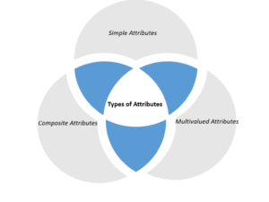
Types of Attributes:
- Simple Attributes: Can’t be broken down further (e.g., Name of a student).
- Composite Attributes: Can be divided into smaller components (e.g., Full Name → First Name, Last Name).
- Derived Attributes: These are not stored directly but are calculated (e.g., age derived from date of birth).
- Multivalued Attributes: Can have multiple values (e.g., Phone Numbers for a customer).
Definition of Entities in ER Diagrams
What Are Entities?
Entities are the foundational elements of an Entity-Relationship (ER) diagram. They represent real-world objects or concepts that a database is designed to store and manage. Think of them as the key players in a database system, each with unique characteristics that help organize and structure data efficiently.
Importance of Entities
Understanding the role of entities is crucial in database design. Let me share a real-world example. When I was designing a database for a university, organizing student data was chaotic. By defining entities such as “Students,” “Courses,” and “Instructors,” each with distinct attributes, I was able to create a structured system that streamlined data retrieval and management. Entities bring clarity and order, ensuring that databases function optimally.
Characteristics of Entities
Entities possess unique characteristics that define their role in a database:
- Uniqueness: Each entity must have a distinct identifier, the primary key, ensuring no two records are the same. For example, in a database of puppies, each puppy could have a unique ID like “Bella123” or “Max987,” preventing confusion and duplication.
- Existence: Entities can often stand independently without relying on others. However, exceptions, such as weak entities, require a strong entity to exist. For instance, “Order Items” in an e-commerce database depend on the “Orders” entity.
- Relevance: Entities must contribute to the overall purpose of the database. In an e-commerce system, entities like “Products,” “Customers,” and “Orders” are essential for managing transactions effectively.
Entity Types and Instances
Understanding the difference between entity types and instances is fundamental in ER modelling:
- Entity Types: These are general categories that group similar entities. Think of “Car” as an entity type representing all vehicles with shared attributes.
- Instances: These are specific members of an entity type. A “Toyota Camry” is an instance of the “Car” entity type, having unique attributes such as model year, colour, and price.

Distinguishing Entity Types from Instances
When I started working with ER diagrams, I struggled to differentiate between entity types and instances. A helpful analogy is to think of entity types as family names (e.g., “Smith family”) and instances as individual family members (e.g., “John Smith”). This perspective makes understanding database structures much more manageable.
Definition of Attributes
Attributes define the properties and characteristics of entities. They are the building blocks that describe an entity’s details, much like how personal details define an individual.
Significance of Attributes
Attributes provide essential information about entities, making data meaningful and searchable. For example, in a bookstore database, the “Book” entity may have attributes like “Title,” “Author,” “Genre,” and “Publication Date.” These details allow users to find specific books quickly.
Types of Attributes
Attributes can be categorized into several types, each serving a distinct function in the database:
- Simple Attributes are indivisible properties, such as a book’s “Title” or “Publication Date.”
- Composite Attributes: These attributes consist of multiple sub-attributes. For example, “Address” can be broken down into “Street,” “City,” “State,” and “Zip Code.”
- Multivalued Attributes: Some attributes can hold multiple values. For example, a book can belong to more than one genre, such as “Mystery” and “Romance.”
Contribution to ER Diagrams
Understanding attribute types ensures a well-structured database model. For instance, if a bookstore database were designed without multivalued attributes, it would struggle to categorize books with multiple genres efficiently.
Role of Key Attributes
Key attributes are critical in data organization and relationships within a database.
Uniqueness and Identification
Key attributes ensure that every entity instance is unique. Examples include:
- ISBN (International Standard Book Number) for books
- Employee ID for employees
- Student ID for students
Building Relationships
Primary keys establish meaningful connections between entities, ensuring data consistency. For instance:
- A “Student ID” links the “Students” entity to “Enrollments.”
- An “Order ID” connects “Customers” to “Orders.”
Visual Representation in ER Diagrams
It’s helpful to visualize these concepts using an ER diagram to fully grasp them. Below is a simple example of how entities, attributes, and key relationships interact:
[Customer] ---- (places) ----> [Order]
  |                                 |
  |                                 |
(CustomerID - PK)            (OrderID - PK)
  Name                           Date
  Email                          TotalAmount
Including visual elements like this in database design documentation enhances comprehension and ensures accuracy.
Key Distinctions between Entities and Attributes
1. Entity
-
An entity represents a real-world object, concept, or thing that can be identified uniquely.
-
In a database, entities are usually represented as tables.
-
Example: A table named “Students” represents the entity Student because each row corresponds to a unique student.
2. Attribute
-
An attribute is a property or characteristic that describes an entity.
-
In a database, attributes are the columns in a table.
-
Example: In the “Students” table, attributes could be Student_ID, Name, Age, and Major, which describe each student.
Key Differences:
|
Entity |
Attribute |
| Definition |
Represents an object or concept |
Represents a property of an entity |
| Representation |
A table in a database |
A column in a table |
| Example |
“Students” (table) |
“Name,” “Age,” “Major” (columns) |
| Uniqueness |
Each row represents a unique entity |
Attributes describe the entity, not unique by themselves |
Attributes Examples
In a database, attributes refer to the properties or characteristics of an entity. Attributes are represented as columns (fields) in a table. Check some examples:
1. For a “Customers” Table
| CustomerID |
FirstName |
LastName |
Email |
PhoneNumber |
Address |
| 101 |
John |
Doe |
john@example.com |
1234567890 |
123 Main St |
Attributes:
2. For an “Orders” Table
| OrderID |
CustomerID |
OrderDate |
TotalAmount |
Status |
| 5001 |
101 |
2024-03-28 |
150.75 |
Shipped |
Attributes:
-
OrderID (Primary Key, Unique Identifier)
-
CustomerID (Foreign Key, References “Customers” Table)
-
OrderDate (Date/Time)
-
TotalAmount (Decimal)
-
Status (String, e.g., “Pending,” “Shipped,” “Delivered”)
Conceptual vs. Physical Representation
conceptual realm to the physical world of ER diagram
Conceptual Representation
In the conceptual world, ER diagrams are designed with the big picture in mind—focusing on data structure and relationships without worrying about implementation details. Think of it like drawing a map of your dream vacation before planning logistics.
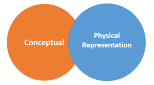
Physical Implementation
When moving to the physical realm, ER diagrams must translate into actual database structures, considering tables, data types, indexes, and constraints. This is like packing your bags for that dream vacation, ensuring you have everything needed.
Example: In a university database, a conceptual ER diagram might define entities like Student, Course, and Instructor, while the physical implementation will include table structures with attributes like Student_ID, Name, Course_Code, etc.
Relationships and Cardinality
Relationships are the backbone of ER diagrams, connecting entities to make databases meaningful and interactive.
Connected Entities
Entities relate through relationships, like students enrolling in courses or customers placing orders. These connections form the essence of data interaction.
Cardinality
Cardinality defines how many instances of one entity relate to instances of another:
- One-to-One (1:1): A university assigns one dorm room to one student.
- One-to-Many (1**:M****):** A customer places multiple orders.
- Many-to-Many (M**:N****):** Students enrolled in various courses, each with many students.
Best Practice: Define cardinality explicitly in ER diagrams using (1,1), (0,N), (1,N) notation for precision.
Entity Hierarchies and Inheritance
Entity Hierarchies
Much like a family tree, entities can be structured hierarchically:
- Parent Entity:
Vehicle
- Child Entities:
Car, Motorcycle, Truck
Inheritance
Entities inherit attributes and relationships from their parent entity, much like inheriting eye colour or musical talent from family members.
Example: A Car entity inherits attributes like Make, Model, and Year From Vehicle, but may also have unique attributes like Fuel Type.
Best Practices in ER Diagram Design
1. Normalization: Keeping Your Database Organized
Normalization is the process of eliminating redundancy and ensuring data consistency.
Eliminating Redundancies: Prevents duplicate data storage, reducing storage costs and errors. Avoiding Anomalies: Prevents update, insert, and delete anomalies for data integrity.
Example: Instead of storing a customer’s address in every order, store it in a separate Customer table and link it to Orders using a foreign key.
2. Abstraction and Simplification
Keep It Understandable: A well-designed ER diagram should be transparent and interpretable.
Avoid Over-Complexity: If a diagram looks too cluttered, consider breaking it into sub-diagrams.
Use abstraction to separate high-level entities from detailed relationships for clarity.
How to Create an ER Diagram (Step-by-Step Guide)
- Identify Entities: List all objects (e.g.,
Student, Course, Instructor).
- Define Attributes: Assign properties to each entity (
Student_ID, Name, Email).
- Determine Relationships: Define how entities interact (
Student enrols in Course).
- Set Cardinality: Specify
one-to-one, one-to-many, or many-to-many relationships.
- Refine and Normalize: Remove redundant data and anomalies.
- Use an ER Diagram Tool: Tools like MySQL Workbench, Lucidchart, or ER/Studio help visualize your database structure.
Common Mistakes to Avoid in ER Diagram Design
- Ignoring Cardinality: Leads to vague or incorrect relationships.
- Overcomplicating Diagrams: Makes it hard to understand.
- Lack of Primary & Foreign Keys: Prevents proper database linkage.
Check also on How to Create ER diagram
Conclusion
Understanding the distinction between entities and attributes is crucial for designing efficient ER diagrams. Entities represent real-world objects, while attributes define their properties. Proper modelling avoids redundancy, maintains data integrity, and supports effective database management. Entities and attributes work hand in hand to structure a database. A well-designed ER diagram ensures efficient data storage and retrieval. If you’re new to ER diagram , try creating a simple database schema using tools like Lucidchart, MySQL Workbench, or ER/Studio.


 Evan John